|
BATTERY HISTORY
The first practical battery, the silver zinc voltaic
pile, was built by Alessandro Volta nearly 200 years ago. For this distinguishing accomplishment the unit of electrical force,
the volt, was named after Volta. Shortly after Volta's discovery the first rechargeable battery was constructed by Johann
Wilihelm Ritter. Unfortunately no practical means existed to recharge it, except from a primary battery. The electric generator
was not to come along for another twenty years so the development of rechargeable technology was essentially stalled for the
lack of a charger. The next significant step in battery development came 60 years latter as George Leclanche introduced his
carbon zinc "wet" battery, a technology that paved the way for today’s common flashlight battery. EARLY LEAD ACID HISTORY
At the same time Plante began studies which lead
to the development of the lead acid cell. It is interesting to note that his early work involved spiral wound cells similar
to the Hawker Energy Products sealed lead battery. In the next 20 year period, Fauare and others developed pasted lead oxide
for the positive electrode and freeing the way for the commercialization of the lead acid battery in telephone exchanges and
railway car lighting. While not a major step in battery development, the selection of the sealed lead acid system by Charles
Kettering of General Motors to support his automotive self starting invention was a major step in the mass production of batteries.
The Germans are credited with the development of gelled electrolyte cells. This was a major step in broadening the application
base for the lead acid system which hear to fore had been limited to rather stationary applications where the chance of acid
spillage was minimized. EARLY NI-CD HISTORY
The nickel
electrode and the alkaline system lagged the lead acid development by 30 years. Edison's experiments in 1890 resulted in the
Nickel hydroxide positive electrode working in conjunction with an iron negative electrode in an alkaline electrolyte to form
the first rechargeable alkaline system. A commercial nickel iron battery targeting the electric car market was demonstrated
in 1910. At the same time, Waldmar Jungner, a Swedish inventor, developed the Nickel Cadmium pocket plate battery. To support
the need for a light weight, high energy battery for their military effort of WWII, the Germans perfected a sintered plate,
flooded electrolyte nickel-cadmium battery that is essentially identical to those used on today's jet military and commercial
jet aircraft. European experimenters designed the first recombinant nickel-cadmium battery in the early 1950's that is the
basis for today's nickel-cadmium industry. BASIC BATTERY TECHNOLOGY
A battery is a device to store electrical energy. It might be considered analogous to
a gas tank on a car except where the gas tank stores fossil energy the battery stores electrical energy. Let's start
with some definitions. The term battery is generally used to describe a single unit comprised of one or more cells. Cells
are the "building blocks" of a battery. A battery can be a single cell which is provided with terminations and insulation
and which is considered ready for use. But usually a battery is a series combination of individual cells assembled in a pack
and provided with some means for connecting to the device it serves. THE BASIC CELL
Every battery has the three basic components. The anode or positive plate, the cathode or negative
plate, and an electrolyte system in which the chemical reaction takes place. Some means for inputting and extracting energy
from the cell must be provided in the form of current collectors. THE
IDEAL BATTERY
If we were to define the attributes for the ideal battery we would come up with the following:
·
It should have a high energy density
· It would be rugged to withstand the rigors of portability
·
It would have a long life
· It would be safe
· It would provide for application flexibility
· And it would be rechargeable.
Lets examine then, what the battery world has available for us. TYPES OF BATTERIES
Batteries are generally classified as either primary or
secondary. Primary batteries are the type that may be used only one time because the active chemicals are used up when the
cell discharges. Once the primary battery is discharged completely, it is discarded. Secondary batteries, on the other hand,
may be used repeatedly because the chemical reaction which produces electrical energy can be reversed by recharging the battery.
TYPES OF PRIMARY CELLS
Primary Cells come in a number
of commercial variations to address different markets. The common zinc-carbon has for years formed the basis for the primary
battery market and still serves for the low end applications because of its low cost. The Alkaline-Manganese is rapidly replacing
the zinc-carbon as the cell of choice for today’s advancing electronics market. It's higher energy density makes it
strong competitor when the hourly operating cost is considered. Mercury-Zinc and Mercury-Cadmium have been popular in the
miniature battery arena where they have been called upon to serve a variety of low power applications ranging from implantable
heart pacers to cameras, hearing aids and watches. Because of environmental implications and technology developments they
are being replaced by other systems. The Air-Zinc battery is finding popularity in a number of low power devices such as the
modern hearing aids and other medical prosthetic devices. Air-Zinc rechargeable batteries are in the development stage. The
thermal battery represents the other end of the primary battery spectrum and are limited to military and scientific specialty
applications. While there are many other primary battery systems that are targeted a specialty applications, none has seen
the surge in popularity like the various lithium systems. The lithium battery, in its many forms, is called upon to power
our microelectronic world for ever increasing applications. PRIMARY
CELL DISCHARGE
If we look at a typical primary cell, the popular alkaline manganese dioxide cell, we see the there basic
components that are found in all cells. The anode, in this case zinc, the cathode, manganese dioxide and the electrolyte system
of potassium hydroxide. As current is drawn from the cell the zinc anode oxidizes to form zinc oxide and the manganese dioxide
is reduced at the cathode to form Mn2O3. The reaction is on way since reversing the current flow will not cause a reverse
reaction required for recharge. TYPES OF RECHARGEABLE CELLS
Rechargeable cells are manufactured in three basic types: The most common is the open type which is typical of our standard
automotive starting battery. The battery is open to the atmosphere and during use gases are emitted and occasional replenishments
of the lost water from the electrolyte is required. A variation, the maintenance free battery merely increases the volume
of electrolyte so the battery will not require maintenance during is service life. The second form is the semi-sealed which
employs some form of electrolyte immobilization scheme to reduce the possibility of acid leakage. These cells are open to
the atmosphere and also release gases during charge and discharge. The so called "gel-cells" fall into this category.
The third type is the fully sealed cell. As the terms imply, during normal operation, a sealed cell does not permit the venting
of gas to the atmosphere, while in an open or semi sealed (sometimes referred to as vented cells), venting is part of the
normal operation. The fully sealed cell requires that the gasses generated when charging the cell be recombined as part of
the process. This recombinant technology is employed in all sealed Ni-Cd and in some sealed lead cell types. Well, so much
for the preliminary definitions. Let's discuss some of the chemistry and construction of the two systems, Ni-Cd and sealed
lead. VOLTAGE
The voltage of any type cell is determined
by wet materials are used in its construction. The total cell voltage equals the sum of the oxidation potential of the anode
and the reduction potential of the cathode. The anode is the positive electrode and the cathode is the negative. The use of
different materials for the anode and cathode yields different cell voltages.
ELECTRODE REACTION | ELECTRODE POTENTIAL | ANODES (-) | * | Zn > ZnO | 1.2
volts | Cd > Cd(OH)2 | 0.8 volts | Pb > PbSO4 | 0.4 volts | CATHODES (+) | * | HgO
> Hg | 0.1 volts | AgO > Ag | 0.3 volts | MnO2 > Mn(OH)2 | 0.4 volts | NiOOH >
Ni(OH)2 | 0.5 volts | PbO2 > PbSO4 | 1.7 volts |
This chart shows some of the common materials used for anodes
and cathodes with their corresponding electrode potential. Adding together the potentials
for the cadmium anode and the nickel
cathode yields the predicted cell voltage for a nickel-cadmium cell, 1.3 volts. As it turns out, actual open
circuit cell voltages are quite close to the predicted values. The same is evident when we examine the Pb and PbO electrodes
of a sealed lead cell. STORED CHARGE
The amount of stored
charge in a cell is determined by how much active material is used. This amount of stored charge, determines the capacity
and is expressed in ampere-hours which is the product of the discharge current and the duration of the discharge. The ampere-hour
rating of cells can be used to compare the capability of cells, but this comparison is really only valid for cells which have
the same chemical system. Cells that use different chemistry should be compared on a variety of factors such as weight, or
power delivery as well as capacity. We will frequently use the term "C" or "C" rate when discussing charge
and discharge rates of batteries. This term "C" is numerically equivalent to the rated capacity of a cell. A cell
discharged at the "C" rate will expend its minimum capacity in one hour. Because nickel cadmium manufacturers establish
their capacity ratings as either the five hour or one hour rate, some manufacturers provide both ratings for ease of comparison.
Sealed lead product line are rated at the ten hour or twenty hour rate but as with nickel-cadmium, some provide ratings at
the five, ten and twenty hour rates for comparison with other sealed lead manufacturers. Some Ni-Cd cells are rated at the
one hour rate. At .25C discharge rate, a cell's one hour rated capacity will be delivered in four hours, and at the 4C discharge
rate, the rated capacity will be delivered in 15 minutes. For example, the "C" rate of a 600 milliampere-hour AA
cell is 600 milliamperes. The.1C discharge or charge rate for this cell would be 60 milliamperes. When discussing battery
applications, the use of "C" rate simplifies understanding the fundamentals of the application and helps normalize
data for easier comparison between different operating conditions. ELECTROCHEMISTRY
OF THE NICKEL CADMIUM CELL
The nickel-cadmium cell is an electrochemical system in which the electrodes containing the
active materials undergo changes in oxidation state without any change in physical state. This is because the active materials
are highly insoluble in the alkaline electrolyte. They remain as solids and do not dissolve while undergoing changes in oxidation
state. This is what makes a nickel-cadmium cell long-lived, since no chemical mechanism exists to cause the loss of the active
materials. An important cell characteristic which results from these chemical and other properties is that the cell voltage
is essentially constant throughout nearly all of the discharge. In the nickel-cadmium cell, nickel oxyhydroxide (NiOOH) is
the charged active material in the positive plate. During discharge, the charged nickel hydroxide goes to a lower valence
state, Ni(OH)2, by accepting electrons from the external circuit. Cadmium metal (Cd), is the charged active material in the
negative plate. During discharge, it is oxidized to cadmium hydroxide Cd(OH)2, and releases electrons to the external circuit.
During charging of the battery, the reactions are reversed, thus returning the cell to the original voltage and capacity.
The electrolyte in which the reaction occurs is potassium hydroxide (KOH) solution in water at concentrations in the 32% range.
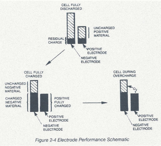
When a cell is overcharged, oxygen gas is generated at the positive electrode, but the sealed nickel-cadmium cell is designed
to accommodate the excess oxygen during slow overcharge with no noticeable loss of performance. This is accomplished by building
the cell with a negative plate which is not fully charged when the positive plate becomes fully charged. Inspection of the
plates will reveal that the negative plate is physically larger than the positive as depicted in Fig 2-4
.
The
excess oxygen quickly passes through the porous separator, reaching the active sites on the negative plate where it is recombined
from the gaseous state forming hydroxyl ions. These hydroxyl ions then move back to the positive plate completing the circuit.
In the unusual instance where a cell is overcharged In the unusual instance where a cell is overcharged at a higher rate than
can be handled by the cell design, a resealable safety vent will open, letting the excess oxygen escape. CONSTRUCTION A cylindrical
nickel-plated steel case (referred to as the cell can) is used as the negative terminal and a cell cover as the positive terminal.
The plates, which are wound to form a compact roll, are isolated from each other by a porous separator, usually nylon or in
high temperature cells, polypropylene. This separator material in addition to isolating the plates, contains the electrolyte
through which the chemical reaction must take place. An insulating seal ring, nylon or polysulphone, electrically insulates
the positive cover from the negative can. The resealable vent mechanism employs an elastomer gasket backed by a steel disk
and held in place by a helical spring to establish the safety valve. 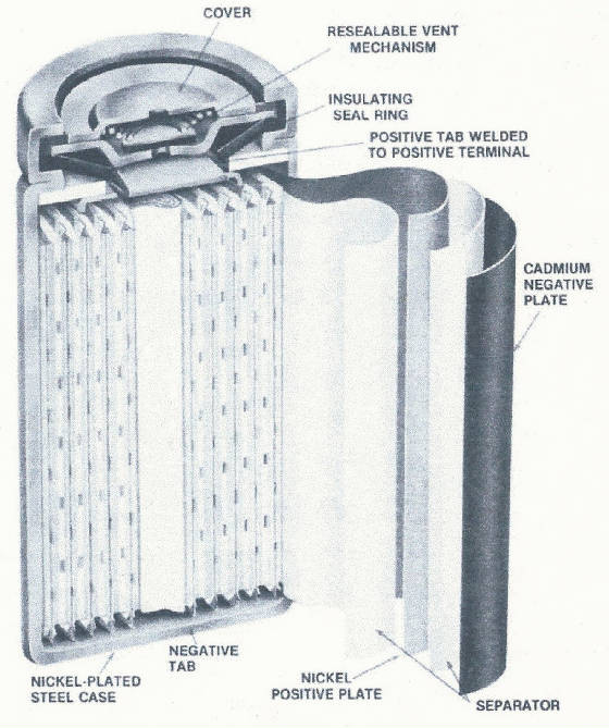
Unlike some designs employing a rubber slug which deteriorates with age
in the caustic environment the spring backed elastomer coated steel disk maintains its sealing and venting characteristics
throughout the useful life of the cell. Other designs have employed a diaphragm, which is pierced by a sharp protrusion in
the cover when excess pressure conditions occur in the cell. While this provides a satisfactory safety vent, there is no resealing
after the vent occurs and the cell rapidly dries out and fails to function. Although most sealed cells currently available
have some form of a vent mechanism, they are still referred to as "sealed" cells. Most manufactures provide this
high pressure vent on its sealed cylindrical cells as a safety measure. CHARGING
Nickel-cadmium cells are charged by applying direct
current with the proper polarity to the cell. The charge current can be
pure direct current, full or half-wave rectified alternating current, or some other pulsating d/c wave form. A nickel-cadmium
cell will charge at rates as low as 0.02C, but the minimum charge rates used in commercial practice are in the range of 0.05.
Charge rates as high as 20C have been used successfully but, as you will see, there must be a means for terminating the high
rate charge before an overcharged state is reached. By industry convention, a charger that fully charges a battery in one
hour or less is called a "fast" charger while one that requires longer than one hour but less than 14 to 16 hours
is called a "quick" charger. Slow chargers require 14 to 16 hours to fully charge, so they are commonly called "overnight"
chargers. These charge times translate to charge rates ranging 0.05C to 0.1C for slow charge, 0.2C to 0.5C for quick charge,
and C or greater for fast charge. Slow and quick charge regimes are popular because of the relatively low cost and simplicity;
of implementation. The charger does not require any special circuitry to switch from a high rate to a low rate as the battery
is capable of accepting a continuous overcharge at the slow or quick charge rates. Most sealed Ni-Cd cell designs today have
built-in overcharge protection due to the capability for the negative plate to absorb the excess oxygen generated at the positive
plate during overcharge. While the cell may be able to recombine the excess oxygen at higher charge rates, the temperature
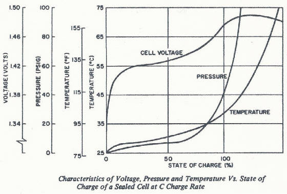
build up can become a significant factor. Then what happens during higher charge rates? To answer this, let's look at a graph
of what happens to voltage, temperature, and pressure as a cell is charged at 0.1 or 0.3C rate.
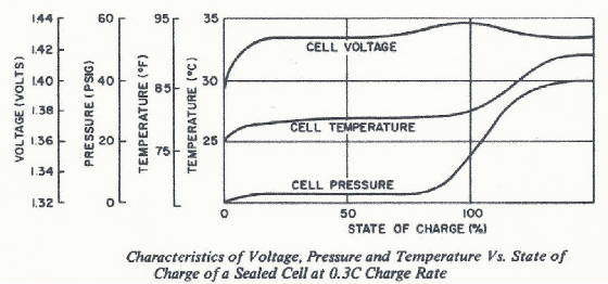
The cell pressure stays low during most of the charge time and rises as
the cell approaches full charge. The higher pressure is the result of the oxygen generation. The higher the overcharge rate
the higher the rate of oxygen generation. Likewise, as the oxygen is recombined on the negative, the cell temperature increases
due to what is termed "the heat of recombination". Since we must adhere to the laws of physics, all the energy going
into the cell must be accounted for. This energy (charge current times the cell voltage) either goes into the chemical conversion
of the active materials (which is an endothermic reaction) or as this conversion nears completion (the cell reaches a full
state of charge) the energy goes into the generation and recombination of oxygen with the resulting temperature rise.
Pressure and temperature curves look far more dramatic a the
C rate chart. Notice how now the pressure and temperature do not level off at an elevated level as seen in the slow and quick
charge situations. Shortly after the cell is fully charged at C rate, the temperature reaches a level that can cause damage
to the cell separator system if this charge current (energy input to the battery) is not reduced.
Sustained high rate overcharge can be accompanied by venting of the cell
causing further damage. Fast chargers (and in some cases, quick chargers where the temperature build up can become significant)
incorporate special circuitry that reduces the charge current automatically as the battery approaches the fully charged state.
While there are many variations, these types of chargers generally employ some scheme that monitors the battery temperature
or voltage profile or a combination of both. The most basic systems employ a simple thermostat or thermistor that measures
the absolute temperature of the battery pack and terminates the charge around 45 C. More elegant temperature termination systems
use a scheme that detects a rise above some ambient temperature. This temperature rise is usually set at 10 degrees C above
ambient. More recently, microprocessor technology has been successfully employed to monitor the rather complex voltage functions
coincident with charging. All of these systems should provide a sustaining charge once the fast charge has been terminated.
It is not uncommon to employ both voltage and temperature monitoring with one serving as a back up for the other to limit
the risk of uncontrolled high rate charge. Charge acceptance
is a measure of how efficiently a cell will charge. The measurement of the acceptance of the inputted energy is the amount
of capacity that can be delivered to a load at a specified temperature as a result of a given amount of charge input to the
cell. If the charge acceptance were 100 percent, then all of the input energy would be available as output. As with most things
in nature nothing is 100%. Ni-Cd cells are no exception. The actual charge acceptance curve typically looks like this, with
excellent efficiency in the 10% to 90% state of charge range.
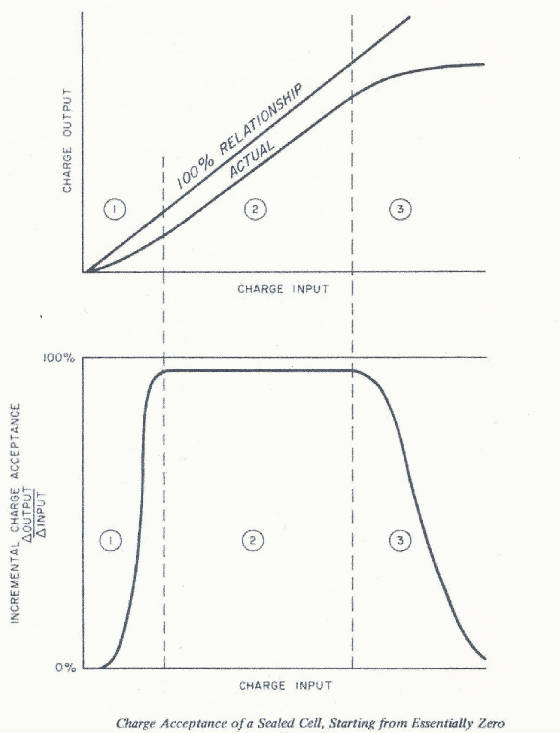
Three areas of the graph display distinct behavior that reflect different
sets of mechanisms causing losses of charge input energy. In area 1, losses are caused by the input energy being used to convert
some of the active material into capacity that will be inaccessible when the cell is discharged. However, this area of inefficiency
gradually disappears as the cell is cycled and this "inaccessible" capacity becomes stabilized. Area 2 shows near
100% charge acceptance. Any inefficiency is caused by parasitic side reactions that take place inside the cell. Area 3 represents
the onset of full charge and overcharge where the cell no longer can accept charge and starts generating oxygen. The cell
once fully charged cannot accept additional charge and the acceptance essentially drops to zero. Charge acceptance is reduced
by slower charge rates. Optimum efficiency is a 1C or 2C rate. These are the plots for charge acceptance at 0.1C and 0.05C.
These lower curves show that the slower charge rates reduce attainable capacity. Higher temperatures also reduce charge efficiency.
Although overall charge efficiencies are never 100%, the optimum charging efficiencies are at room temperature or below. The
key points about charging are: 1. Charging is accomplished
by applying direct current with the proper polarity.
2. Charge rates are categorized into three types: slow, quick,
and fast.
3. At charge rates higher than 0.3C, it is important for the charge rate to be reduced or stopped automatically
when the cell becomes fully charged.
4. Charge acceptance is a measure of a cell's ability to charge. The efficiency
of charging is affected by charge rate and temperature. DISCHARGING
The discharge characteristics of a Ni-Cd cell typically look like this.
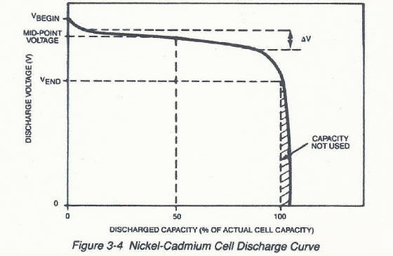
Notice how the cell voltage remains relatively constant at about 1.2 volts
until near the end of discharge. The steep voltage drop at the end of discharge is typical for a nickel-cadmium cell. Under
conditions of actual use, certain variables cause differences in the discharge characteristics of a cell. This means that
these variables need to be considered when estimating actual cell capacity for a certain application. These operating variables
are: -
Discharge rate
- Discharge time
- Depth of discharge
- Cell temperature during charge, at rest, and during
discharge
- Charge rate and overcharge rate - Charge time, Rest time
after charge
- Previous cycling history Every nickel-cadmium cell
or battery has a specific rated capacity, discharge voltage, and effective resistance. Individual cells are rated at 1.2 volts
and voltage for batteries are multiples of the individual cell nominal voltage of 1.2 volts. Five cells connected in series
would result in a 6 volt battery. As you can see, however, the discharge voltage will probably exceed 1.2 volts for some portion
of the discharge period. Most manufacturers rate cell capacity by stating a conservative estimate of the amount of capacity
that can be discharged from a relatively new, fully charged cell. The accepted rating practice is to state a cell rating in
ampere-hours (or milliampere-hours) to a cutoff voltage of 0.9 volts at 5 hour discharge rate. This
graph shows that when rates of discharge are reduced the available capacity becomes less dependent on the discharge rate.
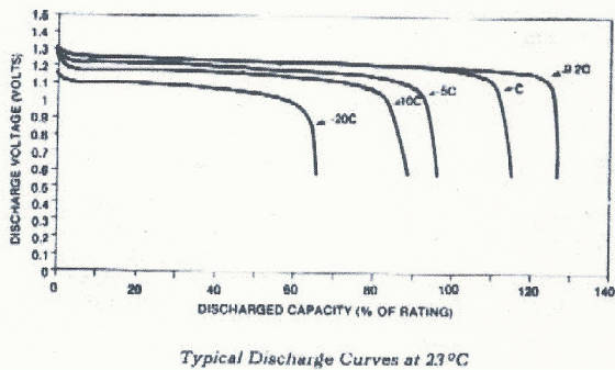
When rates of discharge increase, the available capacity decreases as
the discharge rate increases. The transition from dependent to independent is generally in the C/2 area. Note the "apparent"
advantage that can be gained rating at the 5 hour rate vs. the 1 hour rate. Of interest to the product designer is the real
capacity to the cell at the application discharge rate. Other numbers become academic in this light. EFFECT OF TEMPERATURE ON MID POINT VOLTAGE
Let's look at the effects of temperature on cell capacity.
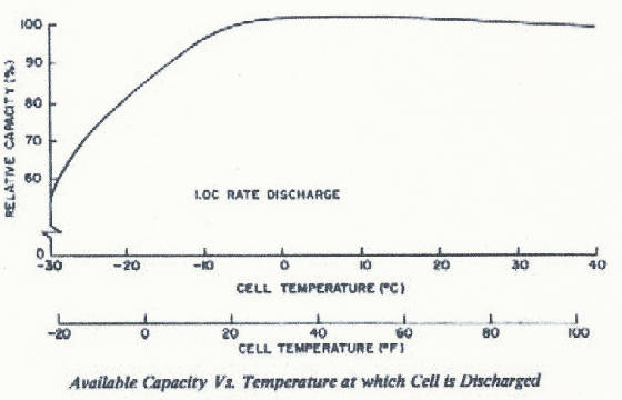
See how at higher temperatures the voltage is lower for the same discharge
rate. When you combine higher discharge rates with higher temperature the voltage profile drops even lower, lowering the apparent
capacity of the cell. Most manufacturers rate cell capacity at 23 degrees C (room temperature) to serve as a guideline for
estimating actual performance. INTERNAL RESISTANCE
The
effective internal resistance, "Re" of the cell is the third characteristic that is usually included in the rating
of a nickel-cadmium cell. This resistance has a dramatic impact on the voltage delivery and hence the capacity to a given
cutoff voltage. Some manufacturers choose to rate their "internal resistance" as the AC impedance at 1000 Hz, which
results in a more "attractive number" rather than employ the ANSI standard that gives a true DC impedance that is
of real interest to the designer. There are a limited number of "AC" applications running from batteries! AC impedance
measurements do provide for a number of diagnostic measurements of the batteries condition but have little to do with predicting
the performance in the application. A cell discharge circuit can be represented as a voltage source in series with the effective
internal resistance.
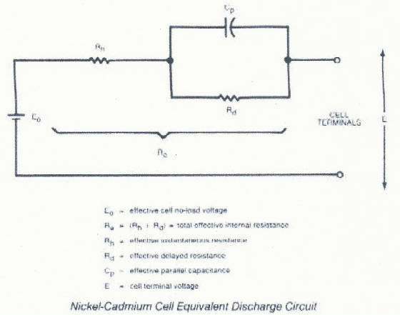
The amount of resistance varies depending upon what portion of the discharge
curve the cell is on. This is reflected in the typical voltage profile. Toward the end of discharge the voltage drops because
of the increase in the internal cell resistance. SELF DISCHARGE
Chemical self discharge causes a cell to lose its energy during storage. This discharge is not harmful to the overall
life of the cell. Full capacity can be restored with a normal charge. These are typical self-discharge rates for nickel-cadmium
cells. RC1 and RC 2 represent different designs.
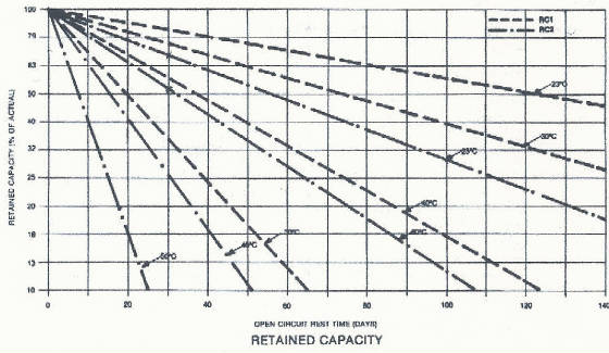
Notice the effect of increased temperature on self-discharge rates. The
rate of self-discharge is about 1% per day at room temperature and doubles for every 10 degrees above room temperature. VOLTAGE CUTOFF
It is important to consider the voltage cutoff of a device
that uses Ni-Cd batteries. Let's look again at the typical voltage profile.
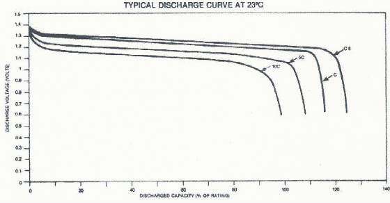
If the voltage cutoff is too high, the battery is underutilized. If the
voltage cutoff is too low, or if there is no voltage cutoff at all, individual cells in the battery can be driven in reverse,
which if done repeatedly, can reduce the available capacity and ultimately shorten the useful life of the battery. The recommended
voltage cutoff depends upon the discharge rate and whether the battery is used in "float" applications or cyclic
applications. Choosing the right voltage cutoff provides the maximum capacity utilization and the maximum reliability. As
the discharge rate decreases the need for a voltage cutoff becomes more important. Use of tapped cell packs for speed control
in power tools and appliances is acceptable because of the relatively high discharge rates involved. At these high discharge
rates the cells exhibit an electrical reversal (due to the rapidly increasing internal resistance at their end of discharge),
which at the high rate precedes the potentially damaging electrochemical reversal, and there is no significant degradation
of cell performance. The key points to remember about discharge characteristics are that nickel-cadmium cells are rated at
1C or C/5 discharge to 0.9 volts at 23 degrees C and have a nominal voltage of 1.2 volts. Cell ratings are conservative design
minimums and actual performance is affected by the conditions under which the cell is charged and discharged. The voltage
profile of a Ni-Cd cell is very flat during most of its usable capacity and it drops off very rapidly when the cell approaches
the end of its usable capacity. Also, it is important that the device to be powered with a nickel-cadmium battery, where voltage
cutoff is employed, has the proper voltage cutoff in order to get the maximum capacity and the maximum reliability. BATTERY LIFE
Battery life can be described in terms of years of service or
number of charge/discharge cycles. Under controlled conditions, a Ni-Cd cell can last up to 10 years with minimum cycling.
On the other hand, cells have been cycled up to ten thousand times, again under controlled conditions. Notice how we say,
"under controlled conditions". Ni-Cd cells employing the same basic technology, are powering satellites for nearly
two decades. The key elements that determine cell life are temperature, overcharging conditions, and, to a smaller extent,
type and depth of discharge. These key factors are tied to the number of cycles and the age of the cells, so both time and
cycling indirectly become elements in determining cell life. We generally define failure as the
point where the cell fails to yield 80% of its rated capacity. The primary failure mode is the loss of separator integrity
that manifests itself in a cell short. This short may be what is termed as a hard short or low resistance or as is typical
in onset of failure, the short is of some finite resistance or "soft" short. This soft short causes the battery
to "self discharge" in a very short period as well as shunt some of the charging energy during the charge cycle
all of which result in what is perceived as a low capacity cell. A functional failure occurs when the cell or battery causes
the end-use device to fail to function. In this case, the cell still has the ability to accept charge and be discharged, but
the performance level is below that necessary to properly run the device. In some cases this type of failure is the result
of an improperly designed piece of equipment or a misapplication of a particular type of battery. The effect of increasing
temperature causes life expectancy to be correspondingly reduced. The percent of rated life decreases dramatically for standard
cells and less dramatically with cells that are designed to be used in higher temperature applications. In overcharge, all
energy delivered to cells is converted to heat. It is
important to not overcharge cells at rates sufficient to cause a significant temperature rise over extended periods of time
because the excess heat will cause a reduction in cell life. A shorted external circuit causes tremendous current flows through
a cell's internal path that can destroy the current collecting tabs and cause the cell to become an open circuit or as a minimum,
damage the cell seal ring causing it to leak. Now let's discuss two common concerns, myths, and misconceptions about Ni-Cd
cells: reversal and memory. REVERSAL
What is cell reversal?
Batteries made up of more than one cell have the potential for cell reversal problems when the discharge is deep enough to
bring one or more of the cells in a battery to zero voltage. If discharge continues beyond this point, the voltage on the
depleted cell will reverse polarity. Here is the general voltage curve as has been shown before, except now it is continued
into the area of overdischarge. The positive electrode is usually the first to run out of capacity. Continuation of the discharge
will cause the reversal of the negative electrode and the voltage will be further reduced to about -1.4 volts. The problem
that occurs is the generation of hydrogen gas. As the electrodes change polarity they will generate hydrogen. Since the hydrogen
will not recombine, the internal cell pressure will build up to a level that causes the cell to vent if the reverse charge
current is maintained for a significant period of time. The solution to cell reversal is to avoid design applications where
the cells will be reversed repetitively or deeply. This is done by selecting a sufficiently high cutoff voltage to assure
that cells will not be reversed. Cell reversal is more damaging at lower rates since the electrochemical reversal occurs at
nearly the same time as the electrical reversal caused by the increase in internal resistance as the cell capacity is depleted.
At higher discharge rates, such as we find in power tools, the electrical reversal occurs before the electrochemical reversal
with a significant fall off in performance of the product. The use of tapped cell packs for speed control in power tools depends
upon this principle and has been tested to verify that there is no damage to the cell pack. Cells received several hundred
cycles of 40% reversal at a 10 C rate, that is the cells were charged in reverse at 12 amps for 40% of their capacity, with
no detrimental effects noted. MEMORY OR VOLTAGE DEPRESSION
Contrary to popular belief, the memory effect is not a loss of cell capacity. Memory is a step in the discharge curve
of a cell.
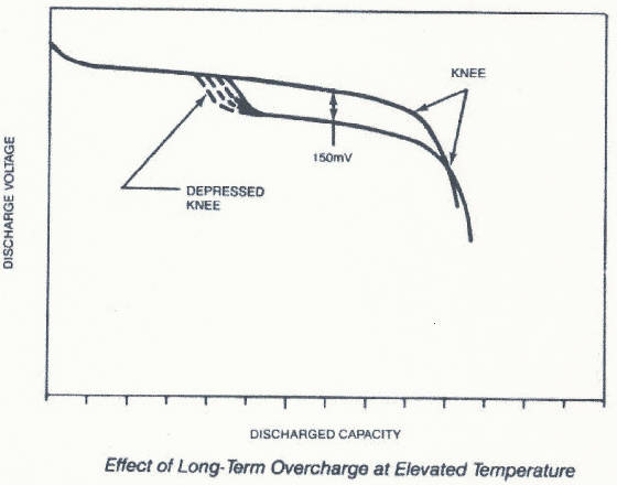
See how the voltage of the lower curve is depressed compared with the
normal discharge curve that we have seen before? The end result of the step is significant only if a device is designed with
too high a cutoff voltage. Most designers take this effect into account and allow for their devices to be run at low enough
voltage to avoid this problem. What causes memory? Actually there are two ways to create a step in the voltage profile. One
is a precisely repetitive partial discharge followed by a slow full charge. The discharge must be to exactly the same point
every discharge in order for this effect to appear. The second and more frequently encountered effect is voltage depression,
which is also called memory. This is caused by continuous overcharge at the overnight rate. If a battery is left on slow charge
for long periods, the crystals of active material in the plates grow larger. As the crystals grow, the surface area of active
material in contact with the electrolyte decreases and this phenomenon manifests itself as a very slight increase in internal
resistance, plus a decrease in the open circuit voltage. The voltage step will occur at different times, depending upon how
long the overcharge occurs and the temperature of the battery in overcharge. As the overcharge continues, the area of voltage
depression will occur earlier in the discharge curve. The area of depression can be removed by one or more discharge/charge
cycles, thereby returning the cell's voltage profile to normal. Today’s cell designs have improved to the point where
this condition is seldom exhibited. EPILOG
Thomas Edison
never knew what he got started over 100 years ago when he invented the first rechargeable alkaline storage battery. Today,
in many areas of our lives, battery powered devices are at work making things more convenient, safer, more productive, and
even more entertaining. Just about any place you can imagine there is a battery system getting things started, or keeping
things going. They're used for very down to earth reasons and for purposes that are literally out of this world. It may have
started with Edison, but even he couldn't possibly have imagined how far battery technology would go. This concludes this
session on sealed nickel-cadmium cells. We hope this has helped you to become more familiar with some of the technical aspects
of sealed nickel-cadmium battery technology and that you now have a better understanding of items that should be considered
when you are developing applications.
|
